I am a mechanical engineer with a background in robotics and space. I specialize in designing lightweight structures and avionics.
I have a strong analytical computing background and extensive experience working with NX, ANSYS, MATLAB. and Excel. My credential include a Masters in Mechanical Engineering from Carnegie Mellon University.
I am passionate about working on hard problems. Over time I’ve gotten a glimpse at a variety of disciplines and subjects; I have found a great curiosity and passion for robotics, structural analysis and simulation, dynamic controls and simulation, and manufacturing. It’s my goal to learn as much as I can about these fields through my studies and hands-on work experience.
Work Experience and Projects
Work Experience
SpaceX
Mechanical Engineer – Starlink Avionics
Overview:
Responsible Engineer for multiple Starlink avionics systems. This includes the flight computer and telemetry system for early V2, and the high-speed data routing system for the entire V2 constellation (thousands of satellites).
Secondary Structure – Designed enclosures, secondary structures, and harnessing interfaces. Analyzed margins for structures, PCB strain, and thermal joints.
PCB Design – Drove the size requirements, floorplan layout, connector selection, mounting locations, and the interface to packaging/enclosure design.
Thermal Analysis – Optimized size/mass of thermally-driven enclosures via sizing analysis, trading layout architectures, heat-spreader design, and thickness tapers.
Manufacturing – Reduced cost and build issues by simplifying assemblies, optimizing parts for machining/stamping/IM, and by supporting production with tooling and part modifications. Designed production tests and analyzed failures.
Photo of Starlink DTC (from T-Mobile Commercial) – The green box represents the Flight Computer and Intra-sat routing system, the yellow box represents the Inter-sat routing and Telemetry Systems.
List of Hardware Ownerships:
FCPU-SNET – Starlink DTC and KU Mechanical assembly for the flight computer and Satnet computer (routes all high-speed data within the satellite) for the DTC variant of Starlink (connects directly to wireless phones anywhere on earth). This was later brought to the KU variant of Starlink (serves internet to User Terminals and is the main Starlink bus).
Gen3 Telemetry Node – Starlink DTC and KU New version of the telemetry system on Starlink. This increased the storage capacity and fixed an issue with SSDs failing during read/write operation by using more rad-hard components.
LSW-Telemnode – Starlink DTC and KU Mechanical assembly for the Laserswitch and Telemetry node and acted as a deployable that opened on-orbit before the solar arrays.
Heat Flux Sensor – A few dozen flights An instrument designed to measure the heat flux at the top of the satellite stack due to Free Molecular Flow after fairing deploy. Early iterations lived on the satellite and this was later moved to the Falcon second stage and ownership was handed off to them.
FCPU Gen6 PCBA – Starlink KU On the newer “Optimized” version of Starlink (currently in production), this new flight computer was designed to be significantly more compact, have more robust/redundant power delivery, and bakes in production and safety improvements for spacecraft charging hazards.
SATNET Gen6 PCBA – Starlink KU This featured an improvement in interconnectivity between satellite payloads, implemented fiberoptic Transceivers, and improved data rate capabilities.
LaserSwitch Gen3.1 PCBA – Starlink KU The Laserswitch routes all traffic between satellites, and this iteration reduced the form-factor significantly, while better arranging the connectors for integration into the satellite.
Network Bay – Starlink KU This mechanical assembly integrated all the high-speed traffic systems on the satellite into one product, and significantly reduced the overall system mass through thermal optimizations. Many manufacturing improvements were also baked in allowing for faster assembly and integration.
SpaceRouter – Starlink V3 This new product will route all high-speed date on Starlink V3 and will offer massive improvements in data-rate capability while reducing the form factor significantly.
Simplified Diagram of the Starlink NetworkPicture of the Satellite Constellation (in 2022)
Boeing Phantomworks
Overview:
Interned over a summer in St. Louis, MO working as a ME and IE
Drafted work instructions for proprietary Advanced Weapons project alongside a senior manufacturing engineer.
Created a 5-year strategy for PhantomWorks Production Engineering facilities via allocating space for new capital equipment, qualifying rooms for production of advanced material systems, and optimizing floor designs
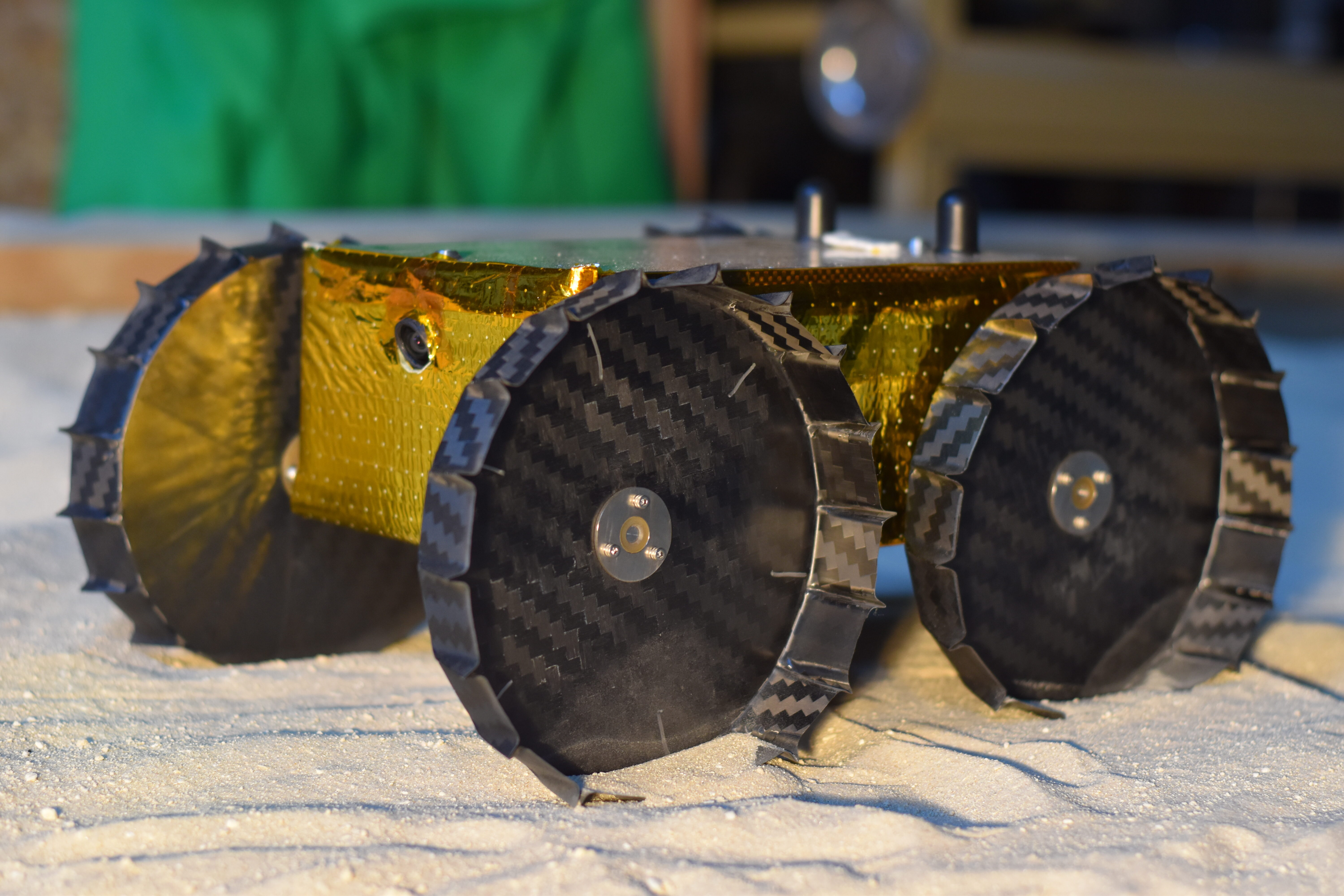
Iris Lunar Rover – Robotics Institute
Mechanical Lead Engineer for Iris Lunar Rover
Overview:
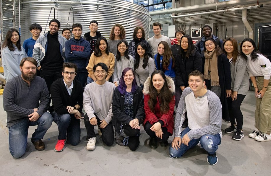
Lead team of 7-15 undergraduate and graduate interns in developing a lunar rover.
Design – Worked on all rover subsystems used in flight model and 4 engineering models.
Structures – Conducted hand analyses and used a FE model in verification.
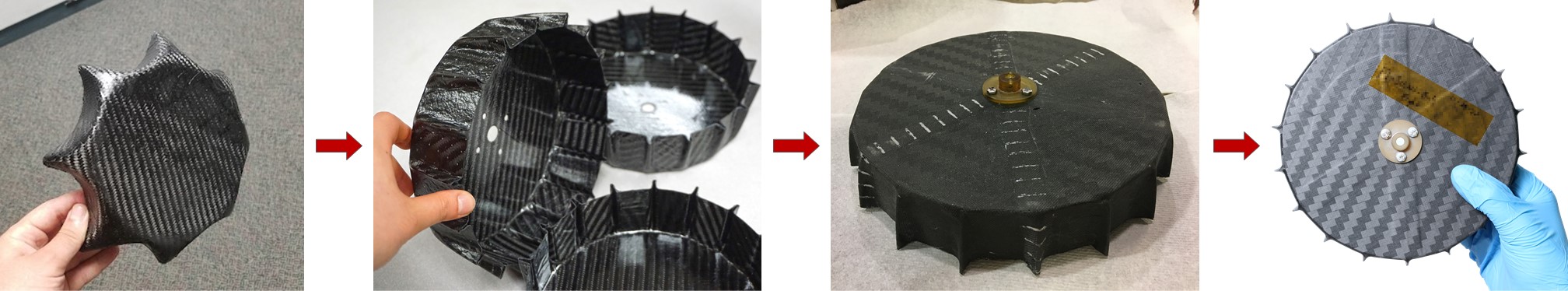
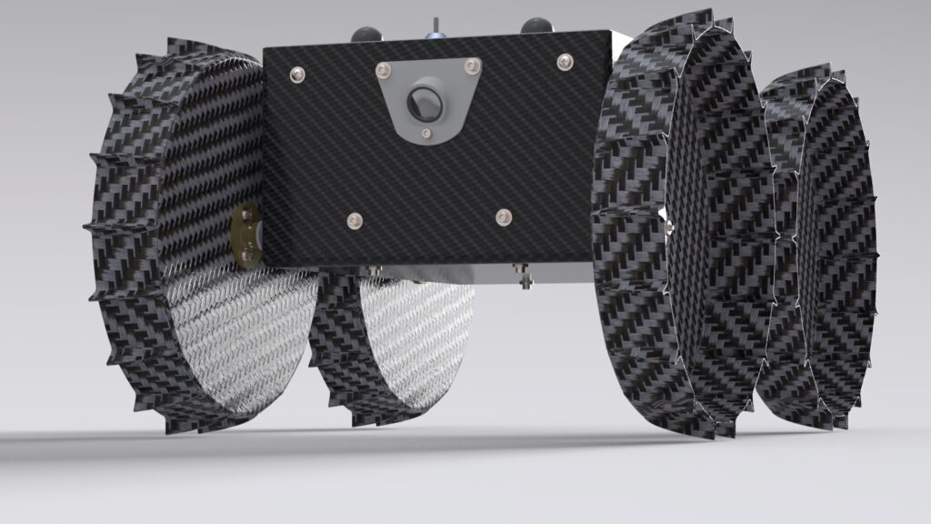
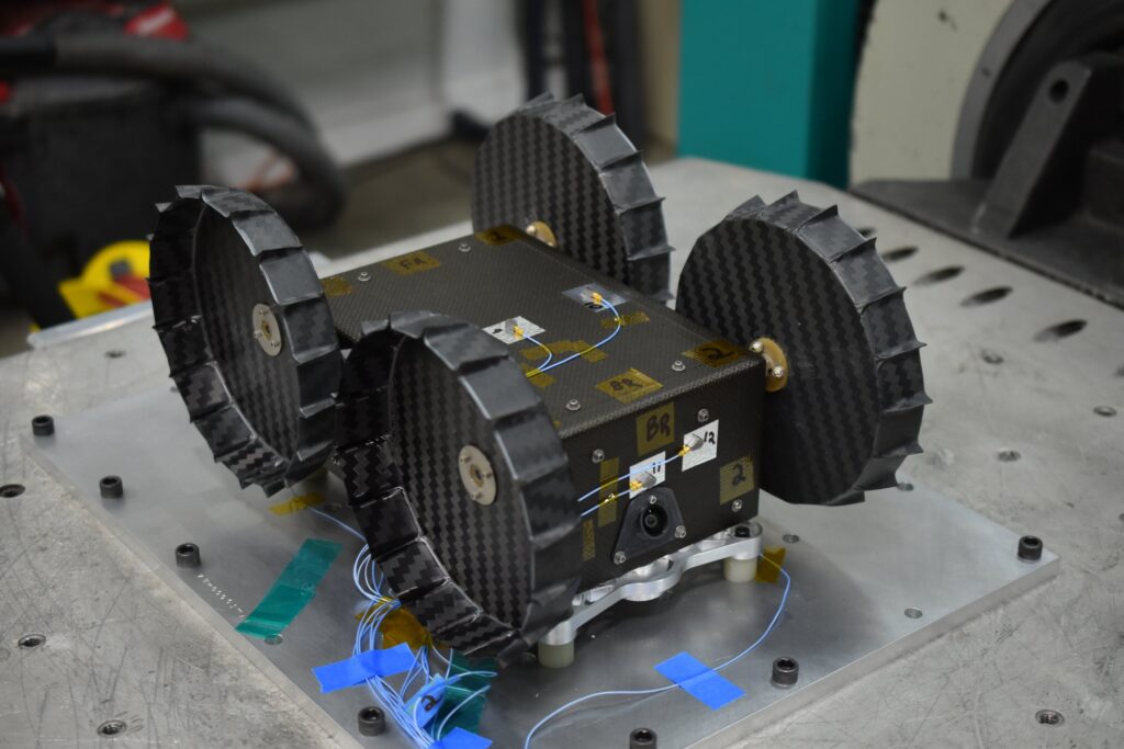
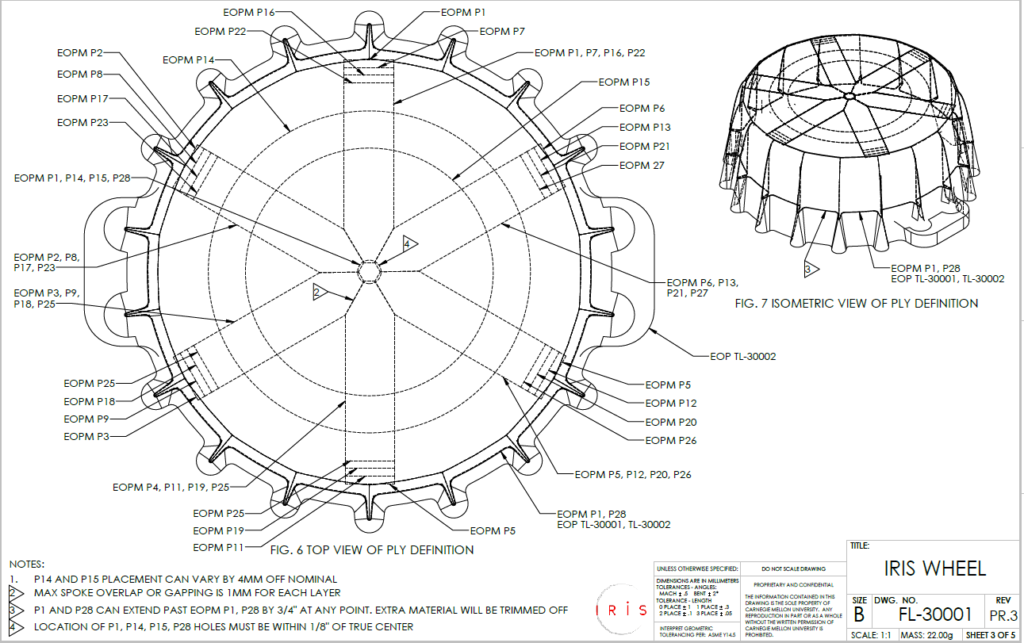
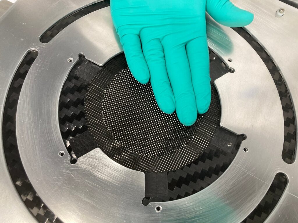
Composites – Led design efforts for all composite structures. Developed tool geometry, ply schedule, and infusion techniques for the innovative and published CFRP “Bottlecap Wheels”.
Testing – Developed plans for and performed static load, vibroacoustic, thermal vacuum, and mobility testing. Generated data analysis on the above tests and helped write test reports.
Technical Drafting – Created and reviewed engineering drawings using ASME Y14 standards.
QC – Developed assembly, composite fab, and inspection procedures using ASME, NASA, and CMH-17 standards.
Iris Mechanical Team Overview
Onboarding
My freshman year at CMU, I joined Red Whittaker’s team to build a lunar nano-rover. I first joined the wheels team, who were trying to test a new type of wheel called the ‘bottlecap’ wheel. I spent the spring working to design a new geometry for the wheel that would allow me to generate tooling that produced sharp and well defined grousers, and avoided gapping and ply bunching. After this proved a huge success, I given a paid position to continue my wheel development over the summer. Over this period, I performed basic structural characterization and prototyping to optimize the ply schedule for our requirements.
The evolution of the ‘bottlecap’ wheel
Leadership: A Baptism by Fire
At the start of my sophomore year, I was given the responsibility of leading the mechanical team for Iris. This was a major challenge for me. At this point, there were very few people remaining from the original team who understood or had experience on the project. My time commitment to the project increased greatly, and I began recruiting, onboarding, and managing my team. At this point, we worked to learn the basics of planetary robotics, aerospace engineering, and to redesign the entire rover system by system. This period allowed me to rapidly improve my abilities designing components and systems using Solidworks. This culminated in building the second engineering model (EM2) to conduct drive testing.
We built a new CAD base, a new simulations model, a new thermal model, new systems requirements, and hurried to build a new engineering model so we might test and iterate our design before our Critical Design Review in Spring of 2020.
Turning Dream into Reality
After passing CDR, we worked furiously to address the many structural and manufacturing flaws of the rover. Over the summer, our team, which only a year ago was totally green, was rapidly becoming more experienced and savvy. Over this time, I built new drawing templates, performed many CAD and drawing reviews, and created many part drawings. This gave me a competent familiarity with ASME drawing standards.
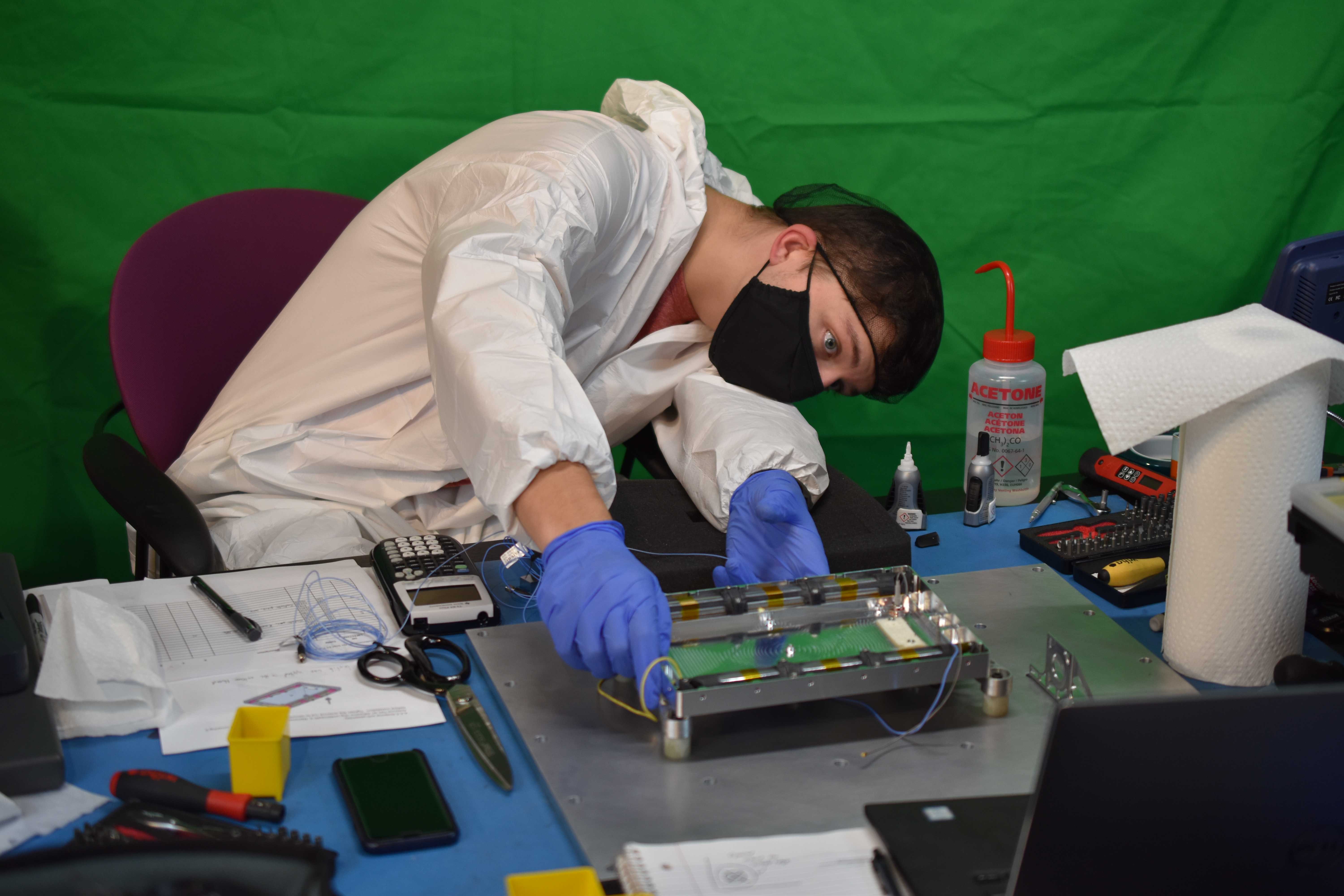
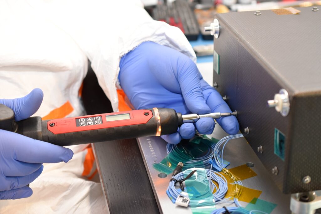
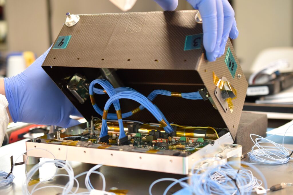
We finally closed the design at the end of the summer, and worked to coordinate the procurement, inventory, assembly, and test planning to validate our design. In September of 2020, we executed a documented and control assembly of our Engineering Model 3 (EM3). This model was used in vibroaccoustic testing, where we conducted a modal survey, static loading well over 50 G, random vibration, and shock testing. Our rover survived without any signs of damage, and our results correlated very well with our structural model. This endeavor forced me to become familiar with NASA testing standards, building and inventory management techniques, assembly planning and execution, and model analysis.
Internal Electronics on Engineering ModelVibration Test on EM3The EM3 design, build, and subsequent testing
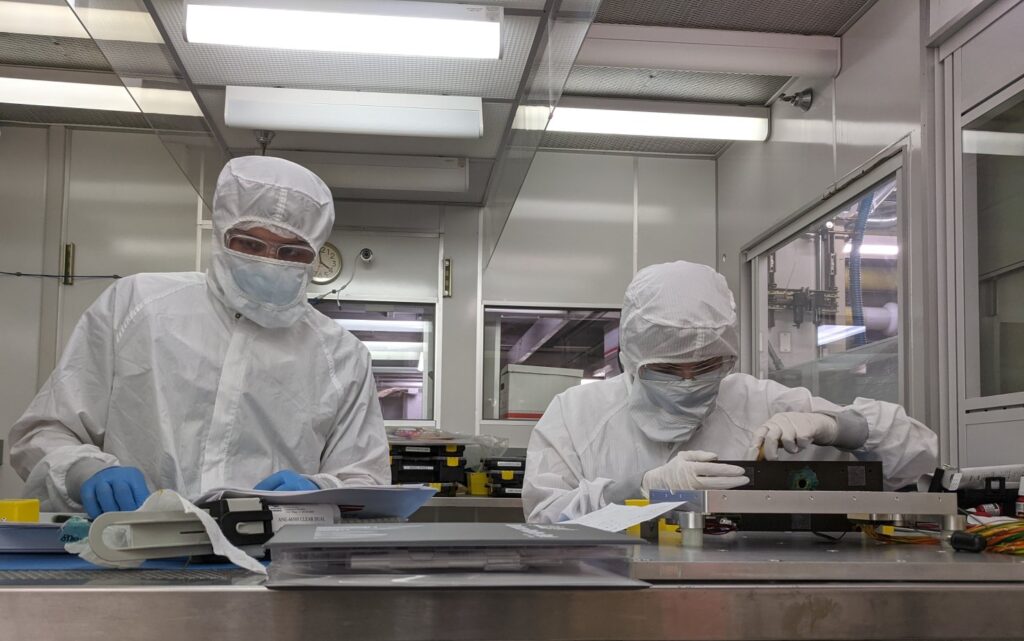
Composites Manufacturing Overhaul
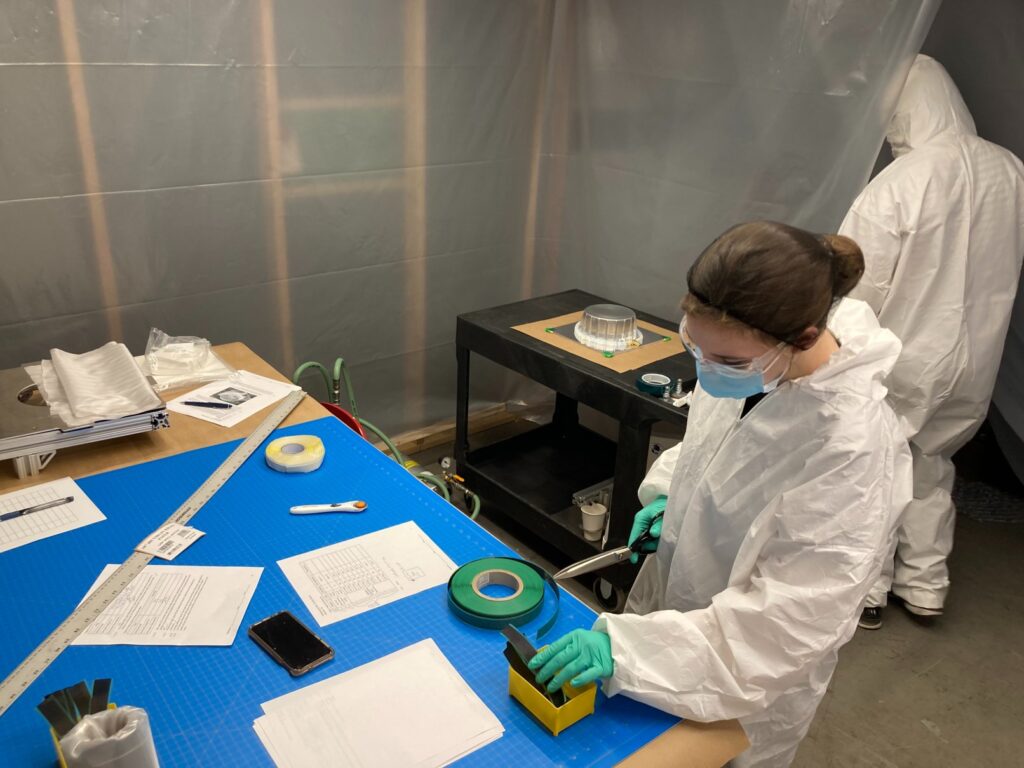
After EM3 proved successful, we set forwards on a mission to improve our composites manufacturing processes, which were well below adequacy for an aerospace program.
We began by building a scrappy in-house composites lab including pseudo-cleanroom. We changed to a resin infusion methodology in order to enable better consistency and to lower the relative resin content. We built fixtures to enable higher positional and directional accuracy during ply application. This culminated in extensive quality control and work plans that formalized and defined our manufacturing methods.
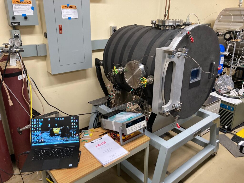
We built an additional model to conduct thermal testing and to function as an additional platform for avionics development. By partnering with Penn State University, we were able to conduct thermal tests in a thermal-vacuum chamber that allowed us to study the behavior of the rover in an environment without convection.
Final Rover Assembly and Integration
After some final design adjustments to accommodate late avionic hardware complications, the final flight rover was built and delivered to Astrobotic.
The Rover has since been fully integrated with the lander and is set to fly in early 2023.
Projects
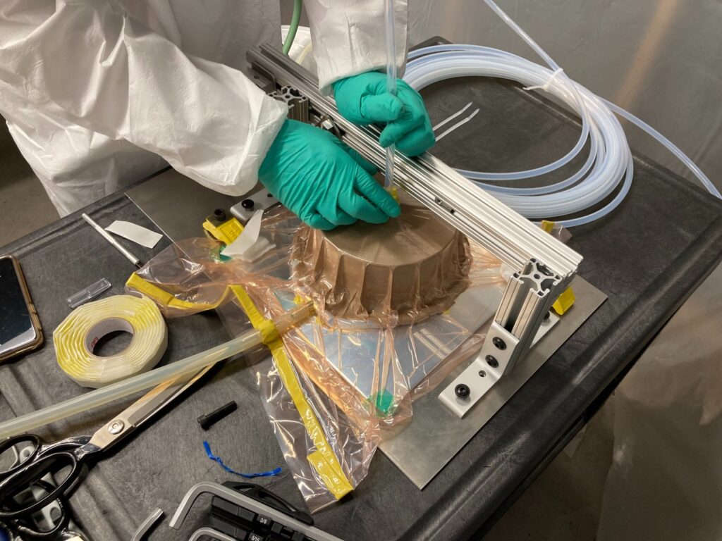
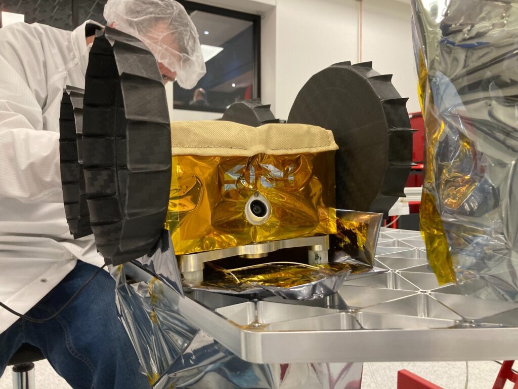
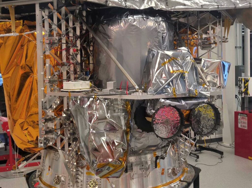
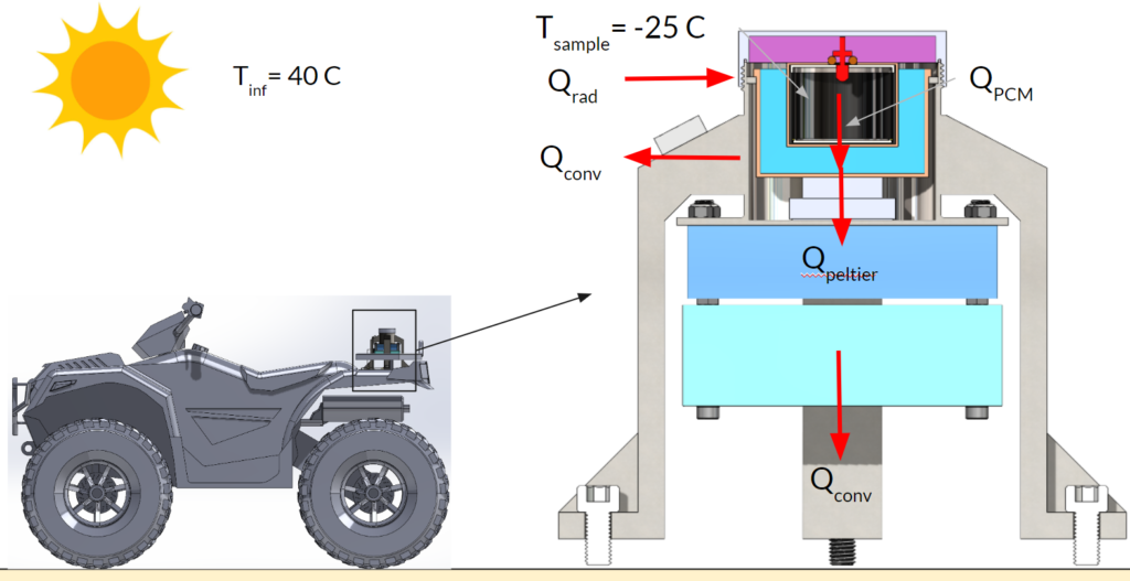
Portable Desert Cryocooler for Preserving Biohazard Specimens
During my senior year at CMU, I was in a team of three that developed a cryocooler that could very rapidly cool specimens down to -25C. By using a 10V power supply from an ATV, it is able to maintain temperatures indefinitely as long as sufficient gasoline is provided.
This was accomplished through:
Multi-modal cooling of sample using:
Phase-change temperature buffer
Thermal-electrical cooling
Advanced insulation provides improved efficiency
Fully static design with exception of simple heat-sink fan
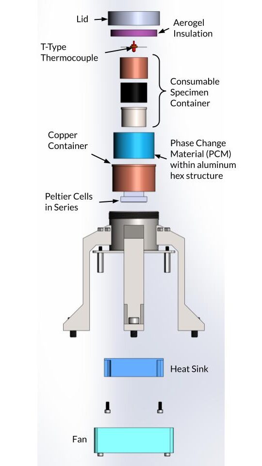
Key Components
A phase-change material (PCM) – Enables ultra-rapid cooling
Two peltier cells connected in series – Continually overcomes environmental heating
Heater – Precise temperature control
Vacuum insulation – Eliminates convection heating and most conduction to specimen
Multi-layered insulation (MLI) – Combats radiation effects between vacuum walls
Aerogel insulation – Reduces heat transfer to the exposed top of sample
Biological packaging – Compliant with medical standards
Includes sterilizable container, absorbent, redundant waterproof seals, etc.
Additionally, we created a novel honeycomb eutectic phase change material composite to increase thermal conductivity through the frozen material. The total mass of phase change material was then calculated using transient analyses.
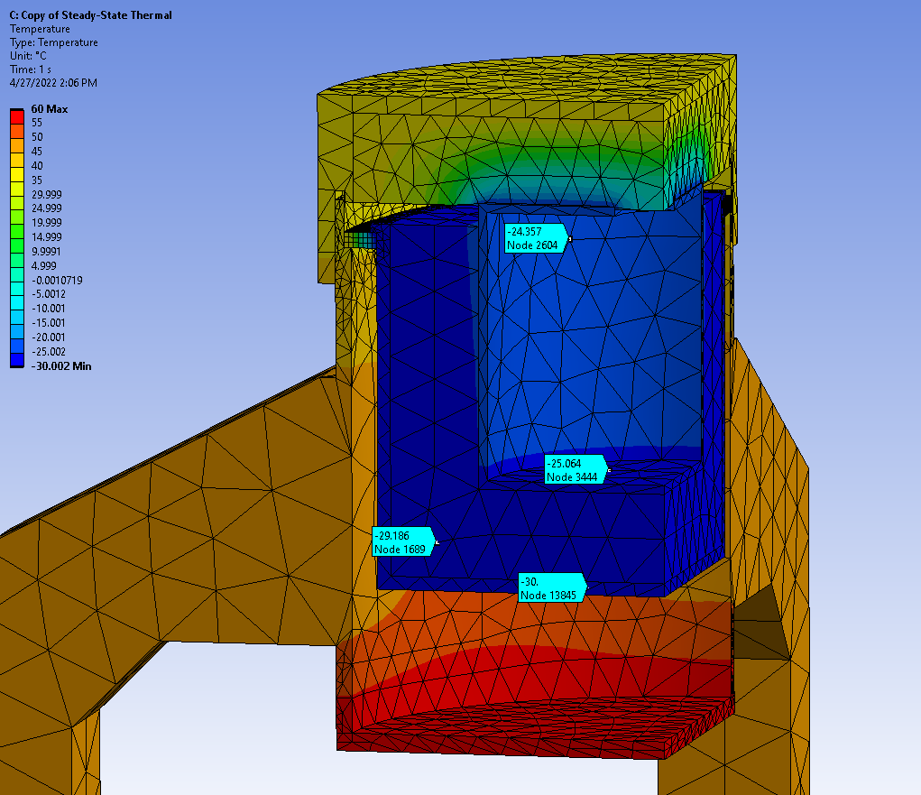
Analytical and finite-element models were developed to drive effective system design and validate component selection.
System Mounted on ATV in Desert Environment
Two steady state models were developed in order to validate the design.
The first model investigates the insulation performance and environmental heating.
The second model determines the needed amount of cooling and heating to maintain a sample temperature of -25C (ideally without melting all the PCM).
Two transient models were then developed.
The first model investigates PCM “thermal capacity” and and conductance to determine if it will be sufficient to rapidly cool the sample.
The second model is a comprehensive simulation of the cooling of the unit from ambient temperature until the sample container is stable at -25C.
Introductory Programming Project
In my first semester at CMU, I took the Fundamentals of Programming and Computer Science class. For the final term project, we were given three weeks to build a complex program using python. For my project, I spent over 100 hours programming a game called Jump Chess, in which I created a new form of chess that included an additional board above the original. Pieces could ‘jump’ up to this second board, adding an extra dimension to the space of play.
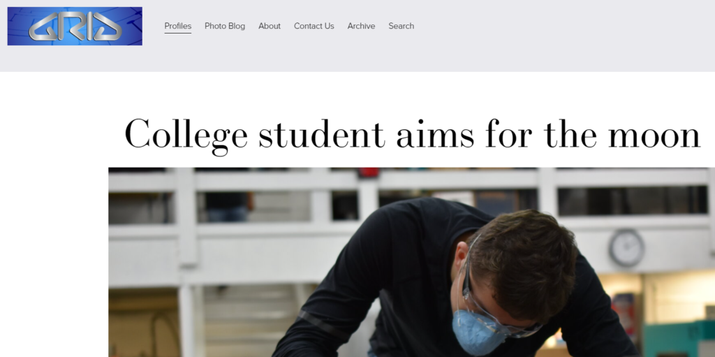
Featured-In
The CFRP ‘bottlecap’ wheels I developed were featured in the premier composites publication CompositesWorld Website version Magazine version (page 16)